© Written by J.Y. WANG
数值风洞模拟范例——
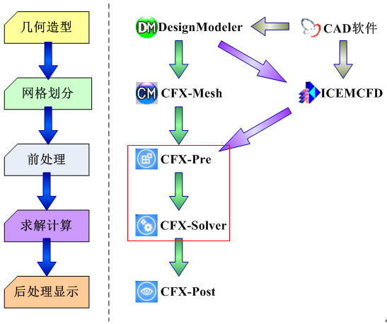
仅CFX前处理及求解定义部分
 |
|
CFD数值模拟过程
|
CFX前处理及求解定义:
1.导入网格(Import Mesh)
2.定义模拟类型(Simulation Type)
3.创建计算域(Domain)
4.指定边界条件(Boundary Condition)
5.给出初始条件(Initial Conditions)
6.定义求解控制(Solver Control)
7.定义输出数据(Output File & Monitor Points)
8.写入定义文件(.def File)并求解
Starting CFX-Pre
1. Prepare the working directory using the following files in the examples directory:
WindProfile.ccl- BluntBodyMesh.gtm
2. Set the working directory and start CFX-Pre.
Defining a Case in CFX-Pre
1. In CFX-Pre, select File > New Case.
2. Select General and click OK.
3. Select File > Save Case As.
4. Under File name, type BluntBody.
5. Click Save.
Importing the Mesh
- Edit Case Options > General in the Outline tree view and ensure that Automatic Default Domain is turned off.
Default Domain generation should be turned off because you will create a new domain manually, later in this tutorial.
- Right-click Mesh and select Import Mesh > Other. The Import Mesh dialog box appears.
- Apply the following settings:
| Setting |
Value |
| File name |
BluntBodyMesh.gtm |
- Click Open.
Importing CEL Expressions
1. Select File > Import > CCL.
2. Ensure that Import Method is set to Append.
3. Select WindProfile.ccl, which should be in your working directory.
4. Click Open.
LIBRARY:
CEL:
EXPRESSIONS:
zb = 10 [m]
ub = 29.2 [m s^-1]
Ht = 350 [m]
Lu = 30 [m]
alpha = 0.16 []
uz = if( z>zb, ub*((z+0.00001[m])/zb)^alpha, ub )
Iz = if( z>zb, 0.1*(Ht/(z+0.00001[m]))^(alpha+0.05), 0.31 )
kz = 1.5*(Iz*uz)^2
ez = 0.09^0.75*(kz^1.5)/Lu
END
END
END
Setting the Analysis Type
- Click Analysis Type.
- Apply the following settings:
| Tab |
Setting |
Value |
| Basic Settings |
Analysis Type > Option |
Steady State |
- Click OK.
Creating the Domain
- Ensure that Flow Analysis 1 > Default Domain is deleted. If not, right-click Default Domain and select Delete.
- Click Domain, and set the name to BluntBody.
- Apply the following settings to BluntBody:
| Tab |
Setting |
Value |
| Basic Settings |
Location and Type > Location |
Fluid |
| Fluid and Particle Definitions |
Fluid 1 |
| Fluid and Particle Definitions > Fluid 1 > Material |
Air Ideal Gas |
| Domain Models > Pressure > Reference Pressure |
1 [atm] |
| Fluid Models |
Heat Transfer > Option |
Isothermal |
| Heat Transfer > Fluid Temperature |
20 [C] |
| Turbulence > Option |
Shear Stress Transport |
Creating the Boundaries
Inlet Boundary
1. Click Boundary.
2. Under Name, type Inlet.
3. Apply the following settings:
| Tab |
Setting |
Value |
| Basic Settings |
Boundary Type |
Inlet |
| Location |
Inlet |
| Boundary Details |
Flow Regime > Option |
Subsonic |
| Mass and Momentum > Option |
Cart. Vel. Components |
| Mass and Momentum > U |
uz |
| Mass and Momentum > V |
0 [m s^-1] |
| Mass and Momentum > W |
0 [m s^-1] |
| Turbulence > Option |
k and Epsilon |
| Turbulence > Turb. Kinetic Energy |
kz |
| Turbulence > Turb. Eddy Dissipation |
ez |
4. Click OK.
Outlet Boundary
1. Create a new boundary named Outlet.
2. Apply the following settings:
| Tab |
Setting |
Value |
| Basic Settings |
Boundary Type |
Outlet |
| Location |
Outlet |
| Boundary Details |
Mass and Momentum > Option |
Opening Pres. And Dirn |
| Mass and Momentum > Relative Pressure |
0 [Pa] |
| Flow Direction > Option |
Normal to Boundary Condition |
| Turbulence > Option |
Zero Gradient |
3. Click OK.
Free-Slip Wall Boundary
1. Create a new boundary named FreeWalls.
2. Apply the following settings:
| Tab |
Setting |
Value |
| Basic Settings |
Boundary Type |
Wall |
| Location |
FreeWalls |
| Boundary Details |
Mass and Momentum > Option |
Free Slip Wall |
3. Click OK.
Wall Boundary on the Blunt Body Surface
1. Create a new boundary named Body.
2. Apply the following settings:
| Tab |
Setting |
Value |
| Basic Settings |
Boundary Type |
Wall |
| Location |
Body |
| Boundary Details |
Mass and Momentum > Option |
No Slip Wall |
3. Click OK.
Setting Initial Values
The initial conditions are consistent with inlet boundaries.
- Click Global Initialization .
- Apply the following settings:
| Tab |
Setting |
Value |
| |
Initial Conditions > Cartesian Velocity Components > Option |
Automatic with Value |
| |
Initial Conditions > Cartesian Velocity Components > U |
uz |
| |
Initial Conditions > Cartesian Velocity Components > V |
0 [m s^-1] |
| |
Initial Conditions > Cartesian Velocity Components > W |
0 [m s^-1] |
| |
Initial Conditions > Static Pressure > Option |
Automatic with Value |
| |
Initial Conditions > Static Pressure > Relative Pressure |
0 [Pa] |
| |
Initial Conditions > Turbulence > Option |
k and Epsilon |
| Global Settings |
Initial Conditions > Turbulence > Turbulence Kinetic Energy > Option |
Automatic with Value |
| Initial Conditions > Turbulence > Turbulence Kinetic Energy > Value |
kz |
| Initial Conditions > Turbulence > Turbulence Eddy Dissipation > Option |
Automatic with Value |
| Initial Conditions > Turbulence > Turbulence Eddy Dissipation > Value |
ez |
- Click OK.
Setting Solver Control
- Click Solver Control .
- Apply the following settings:
| Tab |
Setting |
Value |
| |
Advection Scheme > Option |
Specified Blend Factor |
| |
Advection Scheme > Blend Factor |
0.75 |
| |
Turbulence Numerics > Option |
High Resolution |
| Basic Settings |
Convergence Control > Max. Iterations |
100 |
| Convergence Control > Fluid Timescale Control > Timescale Control |
Physical Timescale |
| Convergence Control > Fluid Timescale Control > Physical Timescale |
2 [s] |
| Convergence Criteria > Residual Target |
1e-05 |
- Click OK.
Obtaining a Solution in Serial
1. Click Start Run.
2. When CFX-Solver is finished, select the check box next to Post-Process Results.
3. If using Standalone Mode, select the check box next to Shut down CFX-Solver Manager.
4. Click OK.
Obtaining a Solution with Local Parallel
To run in local parallel mode, the machine you are on must have more than one processor.
In CFX-Solver Manager, the Define Run dialog box should already be open.
1. Leave Type of Run set to Full.
If Type of Run was instead set to Partitioner Only, your mesh would be split into a number of partitions but would not be run in the CFX-Solver afterwards.
2. Set Run Mode to a parallel mode suitable for your configuration; for example, HP MPI Local Parallel.
This is the recommended method for most applications.
3. If required, click Add Partition to add more partitions.
By default, 2 partitions are assigned.
4. Select Show Advanced Controls.
5. Click the Partitioner tab at the top of the dialog box.
6. Use the default MeTiS partitioner.
Your model will be divided into two sections, with each section running in its own CFX-Solver process. The default is the MeTiS partitioner because it produces more efficient partitions than either Recursive Coordinate Bisection or User Specified Direction.
7. Click Start Run.
8. When CFX-Solver is finished, select the check box next to Post-Process Results.
9. If using Standalone Mode, select the check box next to Shut down CFX-Solver Manager.
10. Click OK.
